Homemade Motorcycle Dyno
A dynamometer is kind of the Holy Grail of shop tools. Commercial units are cheaper and more accessible than ever, but still out of reach for most hobbyists. Even buying time on a dyno is a spendy proposition. What if I told you that its possible [with the help of friends and family] to build a dyno for less than you would pay for a dyno tuning session?
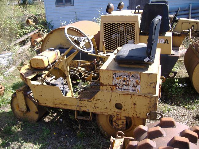
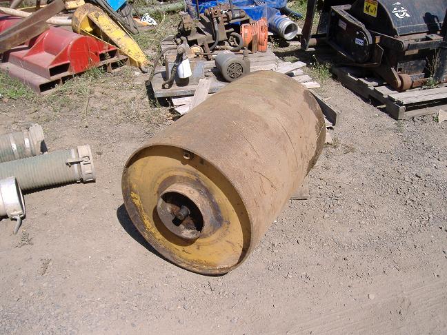
I was talking with my cousin Lucas one day about building a dyno. I had the technical stuff figured out but couldnt come up with a roller. He was working for an excavation company at the time and said he had just the thing.
He got the roller, with bearings, for $20. He also scored the metal for the frame from my Uncle Jeff and designed and built the frame.
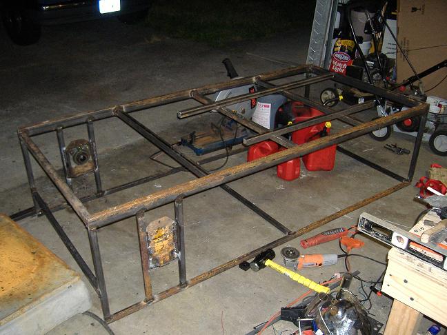
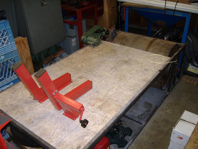
It took him like two days to put this together then it sat in my garage for six years until I got around to doing my part. I bought a sheet of OSB for the deck and added the wheel chock which was given to me by a coworker. The biggest challenge was balancing the roller. That was an entire project unto itself and Ill make a separate page to show the balancing rig.
At this point all weve made is a rolling road test stand. To get any horsepower numbers it needs a data acquisition system. Inertia dynos dont measure torque directly like brake dynos. The torque is calculated based on how fast the roller is accelerating, Force = Mass * Acceleration. The mass doesnt change during a run so all we need to measure is acceleration. But again, we wont measure it directly. I welded a single tooth to the drum and mounted a magnetic pickup to the frame so it will send out a signal once per revolution. What we measure is the time between two signals. From that, we can calculate the speed of the roller, and with two speed calculations we can figure out the acceleration.
My first setup had the magnetic pickup hooked to a USB data logger. I would record the run with the data logger then save it in a CSV format and open it in Excel to do all the math and create a graph. It worked but was cumbersome and not terribly accurate since it was only recording at 10khz.
The next step was to eliminate the data logger and plug the pickup [with clipping diodes across the leads] into the microphone jack on the computer. I recorded the runs with Windows Sound Recorder and saved them as a WAV file. I wrote a program to convert the WAV file into a CSV in the same format as the datalogger. Then I could open the CSV in Excel to do all the math stuff. Still cumbersome but more accurate since the WAV files were 44khz.
To improve on this, I wrote a command line program to create a CSV directly from the soundcard input. Not only is it much easier to use but also more accurate since it samples at 192khz. I had planned to go further and expand the program to eliminate Excel but for now Im happy with this setup.
The only calibration for an inertia dyno is figuring out the inertia of the roller and plugging that into the software. You can find all kinds of equations online for calculating the inertia based on the dimension and material of the roller. That works alright for a simple flywheel but not for my hollow drum of unknown thickness. If you wrap a string around the drum, run it up to a pulley and hang a weight on it, then you can estimate the inertia based on the weight, radius of drum, and the time and distance of the weight falling. I tried that but wasnt confident with results since it was reliant on my reflexes with the stopwatch.
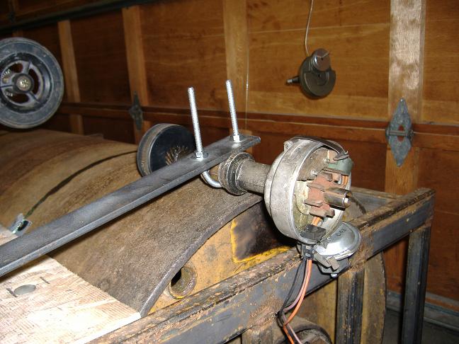
What I did to eliminate the human error was to simply make a dyno pull on the falling weight. The weight and radius of the drum are constant so you should see a flat torque line on a dyno graph. This wouldnt work with the one-signal-per-revolution sensor on the roller since I will get less than two revolutions before the weight hits the floor. To get more signals per revolution I made an auxiliary rotation sensor by drilling a hole in a hockey puck and shoving it onto the end of a distributor. The hockey puck spins 7-3/4 times per revolution of the roller and the distributor puts out 8 signals per revolution, so I end up with 62 signals per revolution of the roller.
With the auxiliary sensor mounted I hung weight on the line to figure out how much force is required just to turn the drum. This weight will be subtracted from the test weight to determine how much weight is accelerating the drum. This takes a bit of trial and error. You need to figure out the lightest weight possible that will fall completely to the floor with just a little nudge of the roller. If it starts falling without a nudge then its too heavy since static friction is greater than kinetic friction. If it doesnt make it all the way to the floor then its not heavy enough. In my case it took 1.6 lbs.
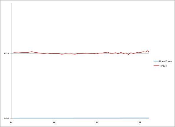
For the actual dyno pull I used an 8.5 lb barbell weight. Subtract 1.6 from 8.5 gives a net weight of 6.9 lbs. The radius of the roller is 0.979 feet so the torque accelerating the drum is 6.76 lb-ft. All thats left then is to make a dyno pull on the falling weight then adjust the inertia value until the graph shows 6.76 lb-ft of torque. For my roller, that ended up being 7.75 lb-ft-sec².
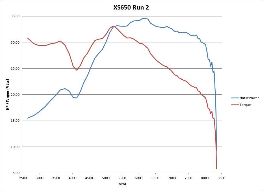
When this video was shot we only had about $70 (and months of labor) into the dyno. Granted, its capabilities are limited but we could stick a bike on there and get a print out of horsepower and torque.
To make this dyno a more useful tool it needs some additions. This is where all the big money is spent.
The first thing I did was buy some beefier tie down straps. I picked up a set from the local motorcycle shop when they were on sale for $25.
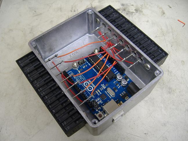
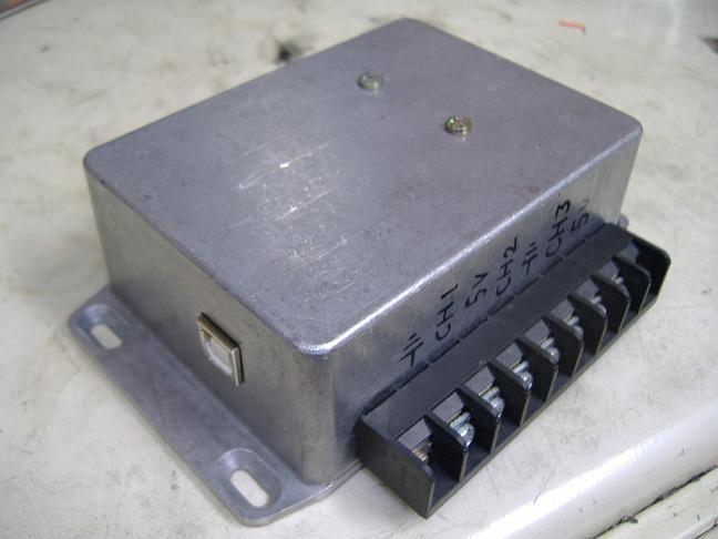
For about $40 I built a six-channel data logger using an Arduino Uno board. It reads the six analog channels and sends them to the computer via USB whenever it receives a signal from the computer. The command line dyno program was modified to record the data logger values during the run. The data logger can read any sensor with a 0-5 volt signal.
For another $110 I built a cooling system using two leaf blowers. The leaf blowers are obnoxious at full speed so I wired them through a light dimmer to vary the speed. The blowers each draw 7.5 amps and an inexpensive off-the-shelf light dimmer is only rated for 5 amps. To make it work, I wired the motors in series and ran it on 240 volts. The capacitors in the light dimmer were only rated for 200 volts so I replaced them with 500 volt caps. I also doubled the farad rating of the capacitor in the timer circuit to keep the timing roughly the same. Were still pulling 7.5 amps through the 5 amp dimmer but it works fine. The triac inside the dimmer is rated for WAY more than 5 amps but they de-rate it since its normally mounted in a wall with no heat sink. I thought I was going to have to add a heat sink to it, but just having it mounted to a metal box out in the open is good enough. It doesnt get hot at all.
So for about $250 we not only have a working dyno, but a useful dyno.
We really should have a brake on the roller so we arent wearing out the brakes on the bike. Ive got a few ideas on how to do it but it hasnt been a big enough priority to warrant spending any time or money on it.
The wheel chock definitely needs some work. The current one is kind of flimsy and we have to unbolt it, drill new holes, and bolt it back down to adjust for wheelbase. Again, Ive got some ideas on what I want but havent got around to making it.
The roller isnt as heavy as I would like. My bike, with me on it, is about 500 lbs. To simulate that inertia with a 23.5 diameter roller, it would need to have a polar moment of 14.9 lb-ft-sec²; (500 * 23.5²) / 18522 = 14.9. I have a 2 diameter steel disc about 2 thick that I dug out of a scrap bin. If I welded that to the side of the roller then it would bring it up to around 12 lb-ft-sec², which is better but still low. Balancing the roller takes a considerable amount of time. Before I go through that again, Id like to find a weight for the other side of the drum so I can hit my target.
If anyone wants to play along at home then here is the software Im using.
DataLog.ino is the "sketch" for the Arduino Uno.
WAVdyno.zip contains WAVdyno.exe and all the files it needs to run. This is the command line program that records the dyno run. You're supposed to be able to run WAVdyno.exe without installing Python, but it only seems to work on my computers that have Python installed.
WAVdyno.py is the source code for the command line recorder. You can run this instead of WAVdyno.exe but it does require Python2.7, as well as pyAudio and pySerial (all free downloads).
DynoCalculator.xls is the Excel workbook that processes the raw data from the command line recorder and creates the table and graph for the run. You can also input your transmission ratios and it will determine optimum shift points and graph the output where the rubber meets the road.
DynoSim.wav is a WAV file that simulates the signal from the dyno. I put this on an MP3 player plugged into the microphone jack of the computer to test the software.
This is dangerous shit! I put this info here to show you what weve done, not what you should do. Just because I havent killed myself doesnt mean that anything I do is safe. If you do build your own dyno then you do so at your own risk.
If you have any questions or comments e-mail me at mrriggs@gofastforless.com .